The LED that wouldn't light up (current debugging saga!)
I hooked up the ESP32, plugged in the power, and tried to make one tiny LED turn on. It didn't. I have been trying to figure out why for two days. Mom, help.
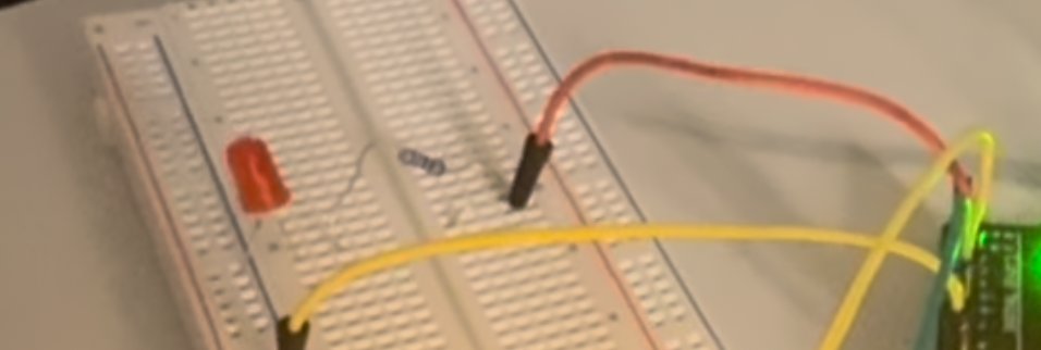
Have you ever tried to build something and the FIRST thing you tested didn’t even work? Yeah. That’s me right now.
I’m trying to upgrade my sensor to use the bigger ESP32 board with all my new parts. I wired everything up. I plugged in the power. And then, to make sure the power was even working, I tried the simplest possible test in the whole world: turn on ONE tiny LED.
It did not turn on.
What I have hooked up
Here’s the actual parts list on my workbench right now (so I don’t forget, and so other kids can copy it):
- ESP32-S AI-Thinker module (the big one with 38 pins)
- 5V Active Piezo Buzzer (for the alarm)
- 16×2 LCD Display with I2C adapter (so it only uses 2 wires!)
- 7805 Voltage Regulator (turns my 9V wall supply into clean 5V)
- Breadboard Power Supply Module (3.3V/5V) + a 0 to 9V power adapter
- Bridge Rectifier (handles raw power)
- Filter Capacitors (so the power doesn’t wobble)
- DHT11 Temperature and Humidity Sensor
- MQ4 Methane Gas Sensor
- Capacitive Soil Moisture Sensor V2.0 (yes! For sensing moisture near food)
- Portable charger, 45W (so it can run without a wall plug)
- Two mini breadboards stuck together (because the ESP32 is too big for one)
- A bunch of male-to-female jumper wires
- One LED (the thing that’s supposed to light up and isn’t)
My current list of suspects
I’m doing detective work. Here are the things I think might be wrong:
- The power supply isn’t actually working. My wall adapter is plugged in. The breadboard power module’s tiny green light IS on. But maybe the rails on my breadboard aren’t actually carrying 5V?
- The two breadboards aren’t talking to each other. I pushed them together so the ESP32 would fit. But the power rails on the two boards don’t automatically connect! Maybe I need a jumper wire to bridge them.
- A loose connection somewhere. (I’ve been burned by this before. See The Loose Wire Saga for last time.)
- The LED is in backwards. LEDs only work one way. The longer leg is +, shorter leg is -. Have I been a goof and put it in wrong?
- The ESP32 needs to be told to power the pin. It doesn’t just send 3.3V to a pin unless my code tells it to. Maybe I forgot to upload the “blink” code.
What I’m going to try, in order
Tomorrow I’m going to do these in order, like a real scientist:
- Multimeter the power rails on BOTH breadboards. Is there actually 5V where I think there is? If not, the problem is upstream.
- Bridge the two breadboards with a red jumper (for +) and a black jumper (for -). Re-test.
- Flip the LED to make sure it’s the right way.
- Upload the “Hello LED” Arduino sketch from the DroneBot Workshop ESP32 tutorial so I know my code is right.
- Try just the LED on the breadboard power, no ESP32 at all. If that doesn’t work, the breadboard power module is the problem. If it DOES work, the ESP32 wiring is the problem.
Why I’m writing this BEFORE I know the answer
A real lab notebook isn’t supposed to only have the wins! Mostly it’s supposed to have the “I’m stuck and here’s what I’m going to try next.” So if you came here looking for the answer, sorry. I’ll update this entry when I figure it out. In the meantime: if you have a guess, please email me.
- Sri (currently staring at an LED that will not turn on)